Click here to return to SWARMS homepage.
This article is
reprinted from R/C Modeler Magazine
and authored BY CHUCK CUNNINGHAM
Click To Visit RCM WEB
Site
Last month we discussed some of the problems and solutions when flying from water with float equipped R/C aircraft. This month let's take a look at floats, what size to use, how to build them, how to install them, and how to enjoy them. There are a number of commercial floats on the market using all types of materials; built-up balsa, fiberglass, molded plastic, and Styrofoam. With so many types to choose from, why worry about building your own? First, you can size your floats exactly to the size of your aircraft. Second, Styrofoam floats are very easy to build, and third, they we very inexpensive.
Last month we very briefly touched on the subject of size. The length of the fuselage is the main factor in determining the length of the float. For most R/C models measure the distance from the back of the prop to the hinge line of the elevator. The length of each float should be at least 75% of this length and not more than 80%; I like 75% best.
Make a scale drawing of the float that you are going to use by applying the dimensions on the float drawings. For example, let's assume that you're going to equip your .60 size model with floats. And let's also assume that the fuselage length is 48" and the span is 66", and that the wing is a rectangular planform with a chord width of l2". Further, let's assume that your model balances at 3 3/4" back from the leading edge of the wing and that the distance from the balance point of your model to the back of the prop is l3".
Working from our design data we find that the overall float length should be 36". From the step forward, the length is 53% of the overall length or, in our case 19". Locating the step 1/2" behind the balance point gives us a float that extends past the prop about 2 1/4 - 2 1/2". The aft end of the float is 47% of the total length, or 17". If you have a model with a very long nose, or the wings are swept back you will probably have to make your floats longer in the nose to accommodate the configuration of your aircraft. Leave the rest of the float design alone, just add what is needed to the nose length. The step height should be roughly 25% of the overall float height.
Long time readers will recognize that I am recycling the same drawing and design information I have given to you in the past, but I know from long experience that many of the current readers are new to the hobby and may not have seen this information before. Many of you older readers might just now be thinking about flying from water also, and have no idea where or when the last time this information was presented, so here it is again.
Next, we need to add a stiff back or spline running the full length of the float. I usually make these from 1/4" plywood, 1/2"-3/4" wide, and the total length of the float. You can either glue this stiff back directly on top of each float, or cut a groove down the centerline of the float large enough to accept the stiff back. It you have a router and table, or know someone who does have this type of tool then you can make a perfect slot by using an end mill type of blade in the router. Glue the stiff back to the foam float with epoxy. After the epoxy has set, drill a series of holes, 1/4" diameter x 2"-3" deep as the drawing shows. It is essential not to overlook this step. Fill each hole with epoxy, then press a 1/4" diameter dowel into each hole. This prevents the stiff back from ripping away from the foam float if there is a botched up landing.
You can finish these floats in several ways by applying balsa wood or 1/64" plywood to each surface, or cover them with EconoKote, which works pretty well with Styrofoam. My personal all-time favorite is to use plastic packing tape about 2" wide. Most of this tape comes in either clear or a light tan color, but I'm looking for this type of tape in a white color. If you know of some white packing tape, please let me know.
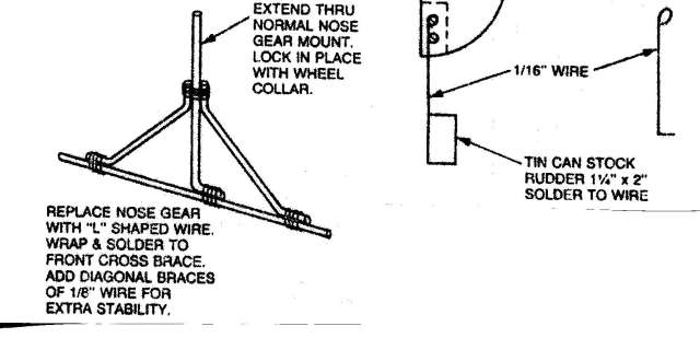
Properly installed, a tape covered float works great and can look very neat. You can carve a rounded contour on the upper surface of the floats, or leave them square. The drawings also show a very simple water rudder. Care must be taken to ensure that the water rudder is in the water when the aircraft is at rest, or floating nose high. When the aircraft is up and running on the step the water rudder should be clear of the water. When moving at high speed the aircraft rudder should be in control of the aircraft, not the water rudder. This is because the water rudder can be so sensitive that it can cause the aircraft to swerve very quickly if it is still in command. A water rudder is a must if you're going to have taxiing control of your aircraft. You can mount a water rudder to the aft end of one or both floats, and naturally this looks more scale-like, but the water rudder attached to the rudder is very simple.
Using the landing gear that your model normally has for land flying is perfectly okay. As a rule of thumb, the landing gear wheel to wheel centeriine should be just about 25% of the wingspan, either taildragger or trike gear. If the span between the floats is greater or smaller, it doesn't make much difference unless your aircraft has a terrible landing gear such as the ME 109. Set the floats on a table, propping them up with some type of shim until the top of the floats are perfectly level with the table top. Place the fuselage of your model on these floats so that (let's assume a taildragger) the main gear is resting on the floats with the balance point of the aircraft just 1/2" or less ahead of the step on the floats. Adjust the height of the rear of your aircraft with some type of shim (a roll or two of paper towels works great) *til the leading edge of the wing is about 3 Deg. positive to the top of the float. 3° works out to about 5/8" positive in a 12" chord, down to 5/16" for a 6" chord. We want the wing to be positive to the top line of the floats because when the aircraft is up and running on the step of the floats, the wing will be trying to lift the aircraft from the water, making for a simple and beautiful take-off. Be sure to check the C.G. after installing your floats. If necessary, you can add weight to the floats to achieve the proper balance. When you are beginning the take-off run you will note that the floats tend to dip into the water a bit due to this positive incidence. Just hold in a bit of up elevator while you advance the throttle, then quickly release the up elevator and let the hull action of the floats take over. Don't try to horse the aircraft off of the water, just let her build up speed moving on the step, then gradually add in a bit of up elevator until your aircraft lifts off. The same idea is true on landings, bring the aircraft into a landing at a higher speed than you normally do when flying from land, as the float equipped model has a higher weight than it did before. Let the aircraft begin to slow down, then try and make an easy three point type of landing on the water. Do not try and make a bash landing as this may rip loose epoxied fittings. Learn to land gentle and smooth.